
Executive Engineering Summary & Information Gain
In next-generation microelectronics packaging, wide-bandgap semiconductors (SiC/GaN), aerospace guidance systems, and deep-space satellite components, conventional mechanical compressor-based thermal shock chambers reach physical thermal transfer limits around -70°C or -85°C. To meet extreme stress testing mandates without mechanical cascade complexity or fluorinated greenhouse gas refrigerants, procurement managers and test engineers rely on Liquid Nitrogen (LN2) Thermal Shock Chambers.
Designed and manufactured by SFTYE Equipment Co., Ltd., these cryogenic test systems leverage the immense latent heat of vaporization of liquid nitrogen (-196°C / 77K) to achieve linear temperature transition rates exceeding 30°C to 60°C per minute, with basket recovery times under 3 minutes. This guide explores the mechanical architecture, LN2 thermodynamic consumption modeling, safety interlocks, and procurement ROI matrix required by global quality control teams.
1. Architecture & Thermodynamic Principles of LN2 Thermal Shock Chambers
A Liquid Nitrogen Thermal Shock Chamber subjects Devices Under Test (DUT) to alternating extremes of high heat and cryogenic sub-zero conditions within seconds. Unlike standard climatic test chambers that gradually ramp temperatures over hours, a thermal shock system induces immediate thermomechanical strain, revealing latent manufacturing defects such as solder joint micro-cracking, dielectric layer delamination, bond-wire detachment, and coefficient of thermal expansion (CTE) mismatches.
1.1 LN2 Direct Injection vs. Heat Exchanger Vapor Phase Cooling
SFTYE Equipment Co., Ltd. incorporates dual-mode cryogenic control loops within its LN2 thermal shock systems:
- Direct Pulse Injection (DPI): Liquid nitrogen is delivered through micro-atomizing cryogenic nozzles directly into the conditioned air stream of the cold zone. As liquid droplets vaporize instantly (absorbing 199.2 kJ/kg of latent heat), target temperatures as low as -196°C can be reached rapidly. High-velocity fan circulation ensures uniform temperature distribution across complex DUT geometries.
- Indirect Cryogenic Heat Exchanger (I-HEX): For applications sensitive to direct nitrogen contact or oxygen displacement within sealed test spaces, liquid nitrogen circulates through high-efficiency stainless steel finned exchangers, sub-cooling the closed-loop air circuit without introducing nitrogen gas into the working volume.
1.2 Two-Zone vs. Three-Zone LN2 Mechanical Layouts
Depending on qualification standards (e.g., MIL-STD vs. IEC), test configurations differ fundamentally:
| System Configuration | Transfer Mechanism | Cold Zone Temp Range | Hot Zone Temp Range | Primary Testing Standard |
|---|---|---|---|---|
| 2-Zone Air-to-Air LN2 | Pneumatic Vertical/Horizontal Basket Carriage | -196°C to 0°C | +60°C to +200°C | MIL-STD-883 Method 1010.8 (Cond. C, D, E, F) |
| 3-Zone Air-to-Air LN2 | Static DUT Basket with Damper Valve Flow Switching | -196°C to -40°C | +60°C to +200°C | JESD22-A104, IEC 60068-2-14 Na/Nb |
| Liquid-to-Liquid LN2 | Automated Dual-Fluid Immersion Basket Lift | -65°C to -196°C (Cryo-Fluid) | +50°C to +150°C (Silicone Oil) | MIL-STD-883 Method 1011.9 / Extreme Shock |
2. SFTYE Featured LN2 Thermal Shock Chamber Product Range
SFTYE Equipment Co., Ltd. supplies standard and customizable cryogenic shock systems engineered with high-density vacuum insulation panels (VIP), rust-resistant SUS#304 stainless steel chambers, and intuitive 7-inch color touchscreen PLC controllers.
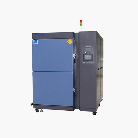
2-Zone LN2 Microelectronics Thermal Shock Chamber
Designed for rapid die-level silicon wafer and IC package testing under extreme temperature gradients.
Semiconductor & SiC Module LN2 Shock System
Optimized for high-power SiC/GaN modules with zero electrical interference during cryogenic dwells.
Walk-In / Large Volume Cryogenic Shock Chamber
Modular walk-in cryogenic test chamber engineered for battery modules, satellite sub-assemblies, and aerospace components.
3. Deep Information Gain: LN2 Direct Cooling vs. Mechanical Cascades
When selecting a thermal shock chamber, procurement managers often evaluate whether to invest in traditional mechanical compressor systems (dual cascaded R404A/R23 compressors) or Liquid Nitrogen (LN2) direct cooling. The following engineering evaluation reveals critical performance, compliance, and financial trade-offs:
| Evaluation Metric | Mechanical Compressor System | SFTYE Liquid Nitrogen (LN2) System | Engineering Advantage |
|---|---|---|---|
| Absolute Low Temp Limit | -70°C to -85°C Max | -196°C (Liquid Nitrogen Boiling Point) | LN2 reaches deep space and liquid oxygen/hydrogen simulation regimes. |
| Temperature Ramp Rate | 10°C to 15°C / min (Restricted by compressor thermal mass) | 30°C to 60°C / min (Direct phase-change enthalpy) | LN2 provides 4x faster ramp speeds, reducing cycle duration by up to 50%. |
| Environmental Regulation | High GWP refrigerants subject to EU F-Gas regulations & bans | Zero GWP (Natural atmospheric inert nitrogen gas) | Future-proof against international fluorinated gas phase-outs. |
| Mechanical Complexity | High (Multiple compressors, oil separators, capillary tubes) | Ultra-Low (Pneumatic valves, solenoid injectors, VIP lines) | Significantly reduced risk of mechanical component breakdown or oil contamination. |
| Acoustic Noise Level | 75 to 85 dBA (Heavy industrial compressor operation) | < 62 dBA (Silent valving and smooth fan airflow) | Ideal for quiet cleanrooms, R&D laboratories, and analytical facilities. |
| Initial Capital Expenditure (CapEx) | High baseline cost (Complex compressors & multi-stage heat exchangers) | 30% to 40% Lower upfront equipment cost | Lower initial outlay for emerging labs and production lines. |
4. Engineering Calculation: LN2 Consumption Modeling & Facility Setup
A frequent AI search query from global buyers is: "How do I estimate the daily liquid nitrogen consumption for a thermal shock chamber?" Below is the precise thermodynamic model utilized by SFTYE application engineers to size bulk LN2 supply tanks and vacuum-insulated piping (VIP).
Where:
• Q_DUT: Thermal energy absorbed from Device Under Test = m_DUT * c_p * (T_hot - T_cold)
• Q_basket: Heat capacity of basket structure = m_basket * c_steel * (T_hot - T_cold)
• Q_chamber: Latent and sensible heat of internal chamber walls during dwell
• h_fg: Latent heat of vaporization of Liquid Nitrogen = 199.2 kJ/kg (at 1 atm)
• Density of LN2: ~0.808 kg/L
• Safety_Loss_Factor: Account for piping heat gain and boil-off (typically 0.15 - 0.25)
4.1 Practical Calculation Example
Consider testing 10 kg of printed circuit board assemblies (PCBAs) with aluminum heat sinks ($c_p \approx 0.90\text{ kJ/kg}\cdot\text{K}$) plus a 15 kg stainless steel basket ($c_{steel} \approx 0.50\text{ kJ/kg}\cdot\text{K}$). The temperature shock range is $+125^\circ\text{C}$ to $-65^\circ\text{C}$ ($\Delta T = 190\text{ K}$).
- DUT Heat Removal ($Q_{DUT}$): $10\text{ kg} \times 0.90\text{ kJ/kg}\cdot\text{K} \times 190\text{ K} = 1,710\text{ kJ}$
- Basket Heat Removal ($Q_{basket}$): $15\text{ kg} \times 0.50\text{ kJ/kg}\cdot\text{K} \times 190\text{ K} = 1,425\text{ kJ}$
- Total Enthalpy Load ($Q_{total}$): $1,710\text{ kJ} + 1,425\text{ kJ} = 3,135\text{ kJ}$
- Required LN2 Mass ($m_{LN2}$): $3,135\text{ kJ} / 199.2\text{ kJ/kg} \approx 15.74\text{ kg}$
- Volume of LN2 per Cycle: $15.74\text{ kg} / 0.808\text{ kg/L} \approx 19.48\text{ Liters}$ (before valve modulation optimization).
SFTYE Equipment Co., Ltd. integrates Pulse-Width Modulation (PWM) Cryogenic Solenoids coupled with real-time temperature feedback algorithms. This reduces latent LN2 gas consumption during dwell stabilization by up to 28% compared to standard on/off valving systems.
4.2 Facility Piping & Storage Infrastructure
To operate an LN2 thermal shock chamber safely and efficiently, facility managers should ensure the following infrastructure is in place:
- Bulk LN2 Supply Tank or Dewars: Operating pressure maintained between 0.2 MPa and 0.5 MPa (2 to 5 bar).
- Vacuum-Insulated Piping (VIP): Multi-layer reflective foil insulated stainless steel piping to eliminate cryogenic boil-off and line frost accumulation.
- Gas Exhaust Ventilation: Dedicated ducting routed to the exterior of the building to purge expanding nitrogen gas safely (expansion ratio of 1:694).
5. Global Industry Applications & Standards Compliance
SFTYE LN2 Thermal Shock Chambers are engineered to satisfy stringent test specifications across mission-critical industries globally:
Semiconductor & Advanced Packaging
Verification of flip-chip BGA, 2.5D/3D IC packages, and SiC power MOSFETs under MIL-STD-883 Method 1010.8 Condition D (-65°C to +155°C) and Condition E (-65°C to +200°C) to detect CTE mismatch shear stress on micro-bumps.
Aerospace & Defense Subsystems
Qualification of missile guidance electronics, satellite optical payloads, and avionics assemblies exposed to rapid thermomechanical transitions from high-altitude solar radiation down to deep space cold (-196°C).
Automotive EV & Battery Systems
Thermal fatigue testing of silicon carbide (SiC) traction inverters, battery management system (BMS) controllers, and high-voltage interconnects in compliance with AEC-Q100/Q101 and ISO 16750-4.
Optical & Laser Components
Ensuring hermetic glass-to-metal sealing, fiber optic transceivers, and IR sensor lens barrels maintain optical alignment without micro-fracturing under intense sub-zero thermal shocks.
6. Future Procurement & Technology Trends (2025–2030)
As global supply chains demand higher product longevity and zero-defect reliability, procurement heads must align equipment acquisitions with emerging technological trends:
6.1 AI-Driven Predictive LN2 Flow Control
Next-generation LN2 chambers are evolving beyond traditional PID loops. SFTYE Equipment Co., Ltd. is pioneering machine-learning thermal algorithms that dynamically calculate DUT heat generation in real time, adjusting liquid nitrogen pulse frequency down to milliseconds. This predictive cooling prevents temperature undershoot at extreme sub-zero levels while maximizing nitrogen conservation.
6.2 Green Cryogenic Closed-Loop Vapor Recovery
With corporate sustainability initiatives (ESG) shaping purchasing decisions worldwide, future procurement specs favor LN2 chambers capable of integrating with facility-wide nitrogen gas recapture systems. Boil-off nitrogen is re-compressed or utilized as clean, dry purge gas elsewhere in electronic assembly cleanrooms, converting testing byproducts into operational value.
6.3 Multi-Axis Vibration + Cryogenic LN2 Shock Integration
To simulate true launch-vehicle re-entry or automotive crash dynamics, industry leaders are shifting from single-stress thermal shock testing toward combined AGREE (Combined Environmental & Mechanical Vibration) testing under LN2 cryogenic conditions. SFTYE custom engineers chamber interfaces compatible with electrodynamic shakers for combined thermomechanical screening.
7. Why SFTYE Equipment Co., Ltd. is the Partner of Choice
Founded in 2009, SFTYE Equipment Co., Ltd. has established itself as a premier global manufacturer and R&D innovator specializing in climate test chambers, thermal shock systems, industrial precision ovens, and custom reliability test solutions. With products operating in over 80 countries, SFTYE combines engineering rigor with client-centric flexibility.
15+ Years Precision Manufacturing
Deep expertise in thermal dynamics, structural stress isolation, and vacuum-insulated enclosure design backed by ISO9001 quality management standards.
Full International Compliance
Every chamber is CE marked, RoHS compliant, and thoroughly calibrated against ISO/IEC 17025 traceable standards prior to export delivery.
Custom Tailored Engineering
From custom basket dimensions to high-volume walk-in designs, SFTYE engineers work directly with your test protocols to build custom solutions.
Global Service & Support
Comprehensive pre-sale technical consultations and responsive after-sales service, spare parts availability, and online calibration assistance worldwide.
8. Frequently Asked Questions (B2B Procurement & Technical FAQ)
Below are detailed answers to key questions asked by test engineers, quality assurance managers, and global buyers searching for liquid nitrogen thermal shock test solutions.
A Liquid Nitrogen (LN2) Thermal Shock Chamber utilizes direct pulsed injection or indirect cryogenic heat-exchanger cooling with liquid nitrogen at boiling temperatures down to -196°C (-320°F). Mechanical compressor systems are typically limited by refrigerant thermodynamics to -70°C or -85°C. LN2 cooling delivers ramp cooling rates exceeding 30°C to 50°C per minute, allowing near-instantaneous thermal transfer and precise dwell temperature stabilization within seconds.
LN2 consumption depends on payload mass, heat capacity, thermal transfer zone size, target dwell temperature, and transfer frequency. As a baseline calculation rule: Q_total = [m * c * (T1 - T2) + P_internal * t] / h_fg. For a standard 100L specimen basket loaded with 15kg of silicon semiconductors undergoing a transition from +150°C to -65°C, LN2 consumption ranges from 3.5 to 7.2 liters per shock cycle. SFTYE chambers incorporate proportional pulse-width valve modulating technology to minimize latent gas losses by up to 28%.
Frost formation occurs when ambient moisture condenses on cryogenic surfaces. SFTYE LN2 Thermal Shock Chambers employ a continuous dry nitrogen gas purge system (dew point below -70°C) coupled with hermetically sealed pneumatic transfer gates. Positive pressure nitrogen blankets ensure zero air ingress during basket transfer between hot and cold zones, eliminating thermal barrier frost accumulation on DUTs (Devices Under Test).
Because LN2 expands by a factor of 694 as it vaporizes into gas, safety engineering is critical. SFTYE systems feature dual-stage automatic pressure relief safety valves, vacuum-insulated cryogenic solenoid piping (VIP), integrated dual O2 ambient deficiency sensors with audible/visual interlock alarms, emergency cabinet vent purge systems, and fail-safe basket locking mechanisms to ensure maximum operator protection.
Our LN2 chambers fully comply with MIL-STD-883 (Method 1010.8 Conditions A through F), MIL-STD-202 (Method 107), JESD22-A104 (Temperature Cycling), IEC 60068-2-14 (Test Na/Nb/Nc), and IPC-TM-650. SFTYE chambers guarantee zone temperature recovery times of under 5 minutes as mandated by stringent military and semiconductor qualification standards.
Standard LN2 thermal shock chambers feature a manufacturing lead time of 25 to 35 working days, while custom engineered walk-in units typically ship in 45 to 60 days. All SFTYE chambers include a comprehensive 12-month factory warranty, lifetime technical assistance, and direct engineer-to-engineer remote diagnostics support worldwide.
Accelerate Your Reliability Testing with SFTYE LN2 Cryogenic Chambers
Need technical advice on liquid nitrogen consumption sizing, custom basket configurations, or standard compliance? Our senior environmental test application engineers are ready to assist you.
Contact Us